
Section 4 - Installing Pedestrian and Double Gates
Use this guide to prepare the opening, assemble and hang the gates, fit the hardware and check that everything works correctly. Install the posts first (see Section 2). Keep the instructions for your specific hinges, lock and latch handy to refer to during installation. Use two people to handle and install gates safely.
4.1 Check before you start
Check the Pedestrian Gate Setout Drawings for your setup.
Check the gate size, style, hinge side and opening direction against your job requirements.
Check posts are plumb, secure and suitable for the gate load. Concrete and chemical anchors must reach the strength required by their manufacturer before the gate is hung.
Measure the clear opening at the top, middle and bottom. Use the smallest measurement to calculate the gate width after deducting the required hinge and latch gaps. Do not assume the opening is square.
Check the full swing path for rising ground, walls, fences and other obstructions.
Confirm any required brace and approved attachment method for this gate size and style. Fit it before final alignment.
Helpful tip: Set the ground clearance to suit the whole swing, not only the closed position.
4.2 Installing a pedestrian gate
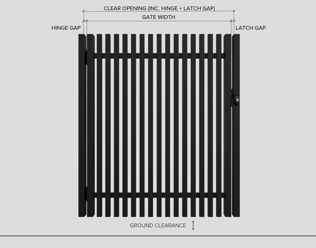
Front view: Diagram is schematic and not to scale. Confirm hinge/latch positions and gaps for the actual hardware supplies.
Instructions
Assemble the gate: Orientate the gate frames so that once inserted, the frames align with the front of the panel. On Blade panels, the blades will sit slightly proud of the frame. Identify your fixing points, which should ideally be on the underside of the horizontal rails and directly behind a batten/blade so that they are hidden from the front view. Press the panel firmly against the frame, then secure them together with the supplied Tek screws: 1 screw per corner, 4 screws in total. Bolts are supplied but are an optional additional fixing method.
Helpful tip: Align the screw with the rear of a batten/blade so it is hidden from the front view.
Fit the hinges to the gate Check the hinge side and opening direction. Viewed from the front, fit the hinges on the front for an outward-opening gate, or on the back for an inward-opening gate. Position them approximately 100 mm from the top and bottom, subject to your preference (if used for pool fencing keep more than a 900mm distance from top of the bottom hinge to the top of the top hinge).
Support and position Place the gate on stable blocks or packers.
Set the alignment Set the top to the intended gate to the same height alignment of the fence line and check the gate is plumb. Follow the suggested hinge/latch clearances from the Pedestrian Gate Setout article.
Helpful tip: If your hinge gap is 10mm, tape 10 mm packers to the gate to set the initial hinge gap accurately.
Mark the hinges With the gate supported and aligned, position the hinges against the post and mark the screw locations.
Drill and secure Drill and fit the hinges. Keep the gate supported until all required fixings are installed.
Helpful tip: Do not over-tighten the screws, as this can strip the threads.
Test the swing Carefully remove the supports and open the gate. Check for sagging. If any adjust the hinges as required to get alignment.
Fit the latch or lock Fit the lokklatch deluxe or mortice lock once the gate hangs correctly and swings freely. Follow Section 4.4, then complete the checks in Section 4.8.
4.3 Adjusting the hinges
Atlantic hinges *video to come*
Follow that manufacturers instructions to adjust both alignment and self-closing or soft-close functions.
Test closing from several positions, including a small opening, as directed by the hardware instructions. Check that the gate closes and latches reliably.
Adjustable gudgeon hinges -*video to come*
Support the gate before adjusting the hinges. Keep the required amount of thread engaged, then tighten or loosen the locking nuts to make adjustments to your gates. Tighten the nuts to lock in position.Gudgeon hinges do not provide self-closing action.
4.5 Fitting locks and latches - videos installing these locks would be good
Hardware
| Install Video | Additional checks
|
Mortice lock
|
| |
Forge lock
| Follow the instructions and template for the exact model supplied
| |
D&D LokkLatch Deluxe
| Follow D&D’s instructions
| |
D&D MagnaLatch Top Pull
| Follow D&D’s instructions. For pool gates, also check the latch-release heights below.
|
Pool gates in Queensland For an outside latch release, the underside of the release handle must be at least 1,500 mm above finished ground level AND at least 1,400 mm above the top of the highest lower horizontal member. Both measurements apply. These heights alone do not establish compliance. Pool certifier to sign off on final approval to be arranged by home owner.
|
4.3 Installing double swing gates
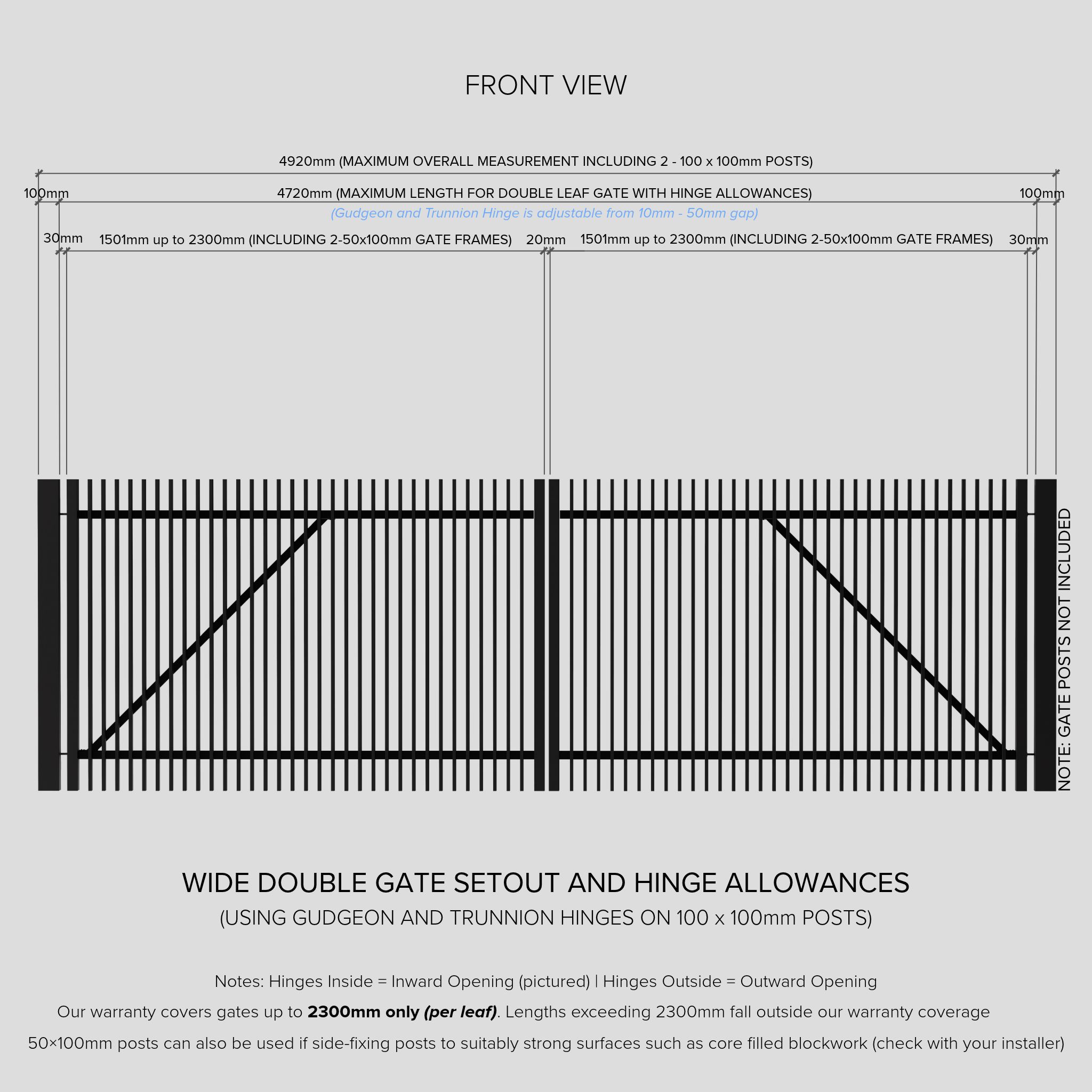
Front view - not to scale.
Example 1 - 4920mm Opening to Outside of Posts
This example uses an overall width of 4920 mm, measured from the outside to outside of the 100 x 100mm posts - this is the maximum width achievable with Future Fence double gates. Note if using 50 x 100 posts side-fixed to walls, the dimension would reduce to 4820mm.
Calculate the clear opening. Subtract the posts from the overall width.
4920mm − 100mm - 100mm = 4720mm between the inside faces of the posts.
Deduct the hinge allowances and centre gap: Adjustable Gudgeon Hinges are best set at 30mm, however in this example we'll use the maximum adjustable range of 50mm to demonstrate the largest width achievable. Generally, allow a 20mm centre gap.
4720mm - 50mm - 50mm - 20mm = 4,600mm.
Calculate the total gate width. Each gate uses a 2200mm panel, with 2 x 50mm gate frames adding 100mm in total.
2200mm + 100mm = 2300mm per gate, or 4600mm for both. This means there is no cutting of the gate panels required, and the hinges can be set at 50mm.
Example 2 – 4250mm Opening Between Block Walls
When 50mm posts are installed inside an existing opening, their widths must be deducted.
Opening between walls: 4250mm
Less 2 × 50mm gate posts: 100mm
Clear opening between posts: 4150mm
Less centre latch gap: 20mm
Less hinge gaps (30mm each side): 60mm
Total width available for both gates: 4070mm
Width of each completed gate leaf (with frames inserted): 2035mm
Width of each gate panel (before frames inserted): 1935mm
Note: Cut each panel to 1925mm before fitting the two x 50mm gate frames.
Helpful tip: Always confirm the finished position of the posts before calculating gate sizes. Measure at several points and check hinge and latch gaps before cutting panels.
Important: The maximum clear opening between the inside faces of the two gate posts must not exceed 4700mm.
4.4 Installing Your Gates
Confirm the hinge and centre gaps suit the chosen hinges and latch before setting the posts. Identify the everyday access leaf and the leaf secured by the drop bolt which will remain fixed in position when the drop bolt is engaged.
Set the gaps Support both leaves in the opening. Double gates may require hinge gaps up to 30mm per side and a centre gap of 20mm, depending on the selected hardware. Confirm the permitted gaps before hanging. Align the tops and check ground clearance through each leaf’s full swing.
Hang and align Follow the hanging method in Section 4.2, using the confirmed double-gate gaps instead of the pedestrian-gate gaps. Test each leaf separately, then close both and check that the centre stiles align with an even gap. Support the leaves before adjusting, then secure all nuts, fixings and retainers.
Fit the operating hardware Fit the specified centre stop, latch and drop bolt. Provide the approved stops or hold-open devices so wind or over-travel does not force hinges and latches beyond their intended movement.
4.6 Gate Bracing Requirements
Braces are not required on 900 and 1200mm high gates. Braces are required on 1500 and 1800mm height gates that over over 1500mm wide.
Installing a required brace
Fit the diagonal brace from the bottom hinge-side corner upward to the top horizontal rail, at approximately 45°.
Use only Future Fence’s approved fixing positions and attachment method. Support the gate during installation, then hang and recheck alignment.
4.7 Fitting drop bolts
1 Position the bolt With both leaves closed and aligned, position the bolt on the intended leaf. Check operating access and clearance from other hardware. Fix the guides to suitable frame sections using the specified fixings.
2 Mark the receiver Check the bolt slides freely. Mark the receiver with the gate in its final closed position. Check for services and confirm the substrate is suitable before drilling.
3 Fit and test Form the hole and fit the specified receiver or sleeve. Clear debris. The bolt must engage without pulling the gate out of alignment and stay fully raised while the gate moves. Fit an open-position receiver only where specified.
CHECKPOINT Test the complete closing order. Both leaves must meet and latch without lifting, dragging or being forced together.
4.6 Fitting the drop bolt
1. Position the drop bolt
Close both gates and align their faces. Hold the drop bolt against the frame you want it to be fixed on to. Adjust the height so the bolt clears the ground when fully raised and extends far enough to engage securely when lowered. Mark the fixing holes for the mounting bracket.
2. Fit the bracket and drill the ground hole
Slide the bolt out of the mounting bracket. Screw the bracket to the gate frame at the marked positions Helpful tip: Do not over-tighten the screws, as this can strip the threads - then slide the bolt back in. With both leaves closed and aligned, lower the bolt and mark where it meets the ground. Drill a hole slightly larger than the bolt diameter.
3. Test the drop bolt
Lower and raise the bolt several times. It should drop into the hole and lift out freely. If it binds, check the alignment first and enlarge the hole slightly if needed. Confirm the bolt clears the ground when fully raised and the gate swings open.
4.7 Troubleshooting
What you notice
| Check and correct
|
Gate drops when supports are removed
| Support it again. Check post movement, hinge fixings are secure
|
Gate rubs or binds
| Check posts and gate for plumb, hinge alignment and gaps. Adjust only within the hinge limits.
|
Gate hits rising ground
| Recheck the entire swing path. Adjust height of gate as long as it is not above the existing post or fence height. Bottom of gate can be cut if required.
|
Latch misses or needs a hard push
| Check the gate alignment first, then adjust gate on Hines or the lokklatch
|
Gate will not self-close or slams
| Adjust the tensioner on the self closing hinges Use the supplied hinge instructions; do not exceed its adjustment limits.
|
Double leaves do not meet evenly
| Check both leaf alignments. Support each gate before hinge adjustment.
|
Drop bolt sticks
| Check the hole and remove debris or lightly enlarge hole.
|
Manufacturer references
Use the instructions supplied with the actual product. Reference pages checked 5 November 2026:
D&D LokkLatch Deluxe Series 3
https://au.ddtech.com/products/lokklatch-deluxe-series-3

DdtechLokkLatch® DELUXE Series 3
Atlantic Multi-Fit Heavy Duty Soft Close Gate Hinge
https://cdn.shopify.com/s/files/1/1003/3886/0311/files/atlantic-multifit-aluminium-pvc-steel-timber-soft-close-hinge-instructions.pdf?v=1779340684

Shopifycdn.shopify.com/s/files/1/1003/3886/0311...
QBCC — Gates, latches and hinges (checked 5 November 2026)
https://qbcc.qld.gov.au/home-owner-hub/swimming-pools/pool-safety-standard/gates-latches-hinges

QldGates, latches and hinges | Queensland Building and Construction Commission